Figure 1 - 2011 NEC Handbook
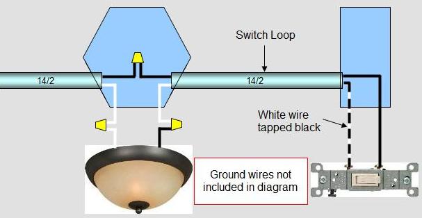
The common method, prior to the implementation of the 2011 NEC code, of physically installing a switch loop was to use standard 14/2 cable which contains a white and black colored wire. In a switch loop situation both the wire that runs from the light fixture to the light switch and the wire that runs from the light switch back to the light fixture are hot or live wires. Prior to the 2011 NEC code it was sufficient to identify the hot wire that was running on a white colored wire by taping the wire with black tape, as shown in Figure 2.

Figure 2 - Diagram of a switch loop
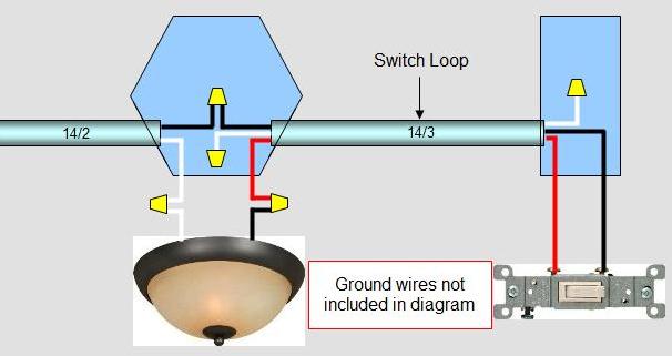
The 2011 NEC code requires that the switch loop use wires of the proper color code to signify hot wires. A white wire signifies a neutral wire. From a physical wiring standpoint it will be necessary, at a minimum to run 14/3 cable which contains a black, red and white wire. Both the black and red colors signify a hot or live wire. The neutral, white wire, which would not be used is simply capped off inside the electrical box. Figure 3 shows the wiring configuration using 14/3 wire in a switch loop.

Figure 3 - Diagram of a new switch loop
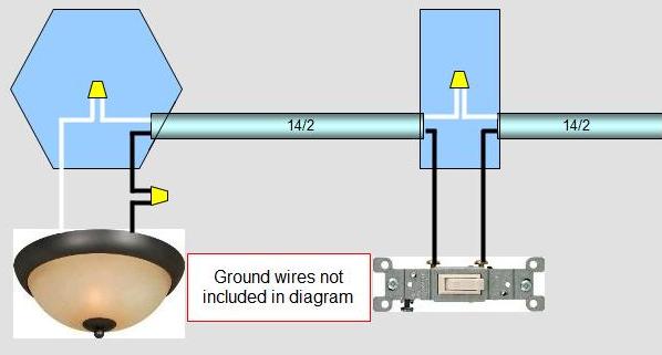
Of course, if you do not wish to run 14/3 cable the easiest method around the problem is to run the power feed for the light fixture into the light switch box, as shown in Figure 4. This avoids the necessity of having to run 14/3 wire and the installation will still meet the NEC code requirements.

Figure 4 - Power feed into light switch
Note: Just because the NEC has published a 2011 code book does not mean that any or all jurisdictions will adopt the switch loop or any other new or modified code. Always check with your local building department to determine if they have adopted all or part of the 2011 NEC code.
