There are numerous methods to heat a home. One method that is becoming very popular is Hydronic radiant floor heating systems. Hydronic radiant heating is characterized by the use of heated water, pumped through plastic piping residing under the floor (as shown in Figure 1), in a home or other structure, using a circulation pump.
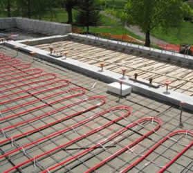
Figure 1 - Polyethylene pipes to be encased in poured concrete slab
Hydronic radiant heating operates as a closed loop system. The heated water transmits its energy to the flooring material which in turn cools the water. The circulation pump returns the water to a boiler or other heat generation source, reheats it and sends it back through the piping system.
Radiant heating provides much better overall room heating than forced air does, as shown in Figure 2.
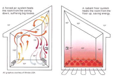
Figure 2 - Radiant heat versus forced air
There are numerous ways to install hydronic radiant heating systems in the floor and not all of the piping systems must be encased in the flooring material.
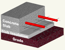
Figure 3 - Hydronic system piping in concrete slab
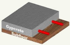
Figure 4 - Hydronic system piping in lightweight concrete
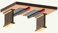
Figure 5 - Hydronic system piping installed under sub-floor between floor joists
- The piping or system tubing for the hydronic radiant heating system can be encased directly in a concrete slab. The concrete slab provides a high thermal mass, retaining and spreading the heat evenly across the slab. This method is generally not a retrofit and is used on new construction. The polyethylene tubing that makes up the heated water delivery system is attached to the rebar or wire mesh that is part of the concrete slab construction, see Figure 3. To obtain the best heating system, and prevent heat loss through the bottom of the concrete slab it is important that the insulation between the slab and the ground be properly installed and of the best quality.
- To obtain a thermal mass after a concrete slab has been poured one can use a lightweight concrete such as gypcrete, as shown in Figure 4. Using a lightweight concrete over an existing concrete slab, allows the homeowner to use hydronic radiant heating as a retrofit, providing that finished floor height is not a problem as well as replacing the finished floor. The finishing flooring material is installed on top of the lightweight concrete in the same manner as one would install it over the an original concrete slab.
- If the finished floor is in place or if finished floor height is a potential problem then a retrofit installation can be accomplished by mounting the hydronic piping system to the underside of the subfloor, between the floor joists, as shown in Figure 5. Installing the hydronic piping system to the under side of the subfloor does not provide the thermal mass that one gets by placing the tubing directly in the concrete slab or in lightweight concrete and hence the total system is not as thermally efficient as either one of those methods. However, as a retrofit it can be installed economically.
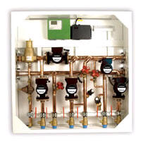
Figure 9 - Manifold for hydronic radiant heating system
Most hydronic radiant heating systems have multiple zones which are controlled by individual thermostats. These zones are fed by a manifold allowing the heated water to only be delivered to those areas of the home which require heating (see Figure 9).
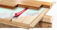
Figure 6 - Hydronic system piping installed in Warmboard®
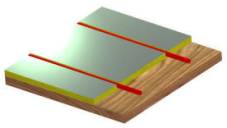
Figure 7 - Hydronic system piping installed in channel panels
- If you are in a situation where you want hydronic radiant heating and have the ability to remove the subfloor material you can use a relatively new product on the market
Warmboard®
. This product takes the place of the subfloor and provides channels for the insertion of the hyrdronic piping system, as shown in Figure 6. The product provides a thermal mass and provides room heating quite quickly. It also allows the installer to use most finished flooring materials including; ceramic and porcelain tile, marble, granite and other natural stones, vinyl, hardwood, laminate and carpeting. - You can install a hydronic radiant system that is sandwiched between the sub-floor material and the finished flooring material. These systems, known as
above floor systems
, use a panel, with an aluminum finish on the bottom and groves on the top to act as a channel for the polyethylene tubing, as shown in Figure 7 and 8 and Table 1. The panel only holds the polyethylene tubing in position horizontally but serves to protect the tubing vertically, as the top of the tubing sits flush with the top of the panel.

Figure 8 - Polyethylene tubing in panel channel, on sub-floor with finished floor above
Table 1 For Figure 8 |
||
1 - Finished flooring |
2 - Panel for housing polyethylene pipe |
3 - Aluminum foil backing |
4 - Sub-floor |
5 - Polyethylene tube resting in channel |
|
The common panel sizes are 7 inch and 10 inch wide and 4 feet long, designed with channels to hold 5/16 inch polyethylene tubing (PEX). Panels are installed individually or in groups of 6 for installation convenience, where they are fan folded and held together with a fiber tape. End panels that provide a 180 degree turn for loop continuity are also available.
