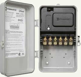
Electrical contactors, as shown in Figure 1, are switches that are turned ON
and OFF
with electrical power rather than with the direct push of a button or flipping a toggle switch.

Figure 1 - Electrical contactor

Figure 2 - Plug-in relay
For all intent purposes, a contactor is a relay, as shown in Figure 2. The term relay
is used in the electronics industry and is usually applied to switching devices in low voltage circuits. Whereas the term contactor
is used in the electrical industry and is usually applied to switching devices in high voltage circuits.
Electrical contactors are used extensively in major appliances, such as refrigerators and ranges. However, they have a multitude of applications.
In order to have an electrical driven device turn ON
and OFF
it is necessary to place a switch in the circuit. Figure 3 shows a basic electrical circuit with a switch controlling a load. The switch is in the open
position, hence the light is not on. In this example the load is a light bulb, but could be a motor, pump, solenoid, or any other electrical powered load.

Figure 3 - Basic electrical circuit with switch open
Figure 4 shows the same circuit with the switch in the closed position, hence the light is on.

Figure 4 - Basic electrical circuit with switch closed
Whereas a switch is turned ON
and OFF
using manual power, a finger. A contactor is turned ON
and OFF
using an electrical circuit.
There are two basic uses for contactors in a home, in some cases the contactor is installed to perform both uses:
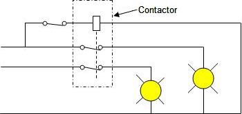
- Controlling a number of different circuits with one switch. Figure 5 shows two electrical circuits being controlled by a contactor with 2 independent switches. The contactor receives its power from one of the light circuits. The switch that controls the contactor's action is closed, hence the switches that control the lights are also closed.
In a home a situation, such as this, may be relevant if a homeowner wanted the ability to turn on all of the landscape lighting around his home with one switch, when the landscape lighting is on two or more circuits.
The switch that controls the contractor could be a toggle or push-button switch or it could be a motion sensor or timer.
The switch that controls the contractor could be a toggle or push-button switch or it could be a motion sensor or timer.
Another example could be the need to turn on light fixtures at the top and bottom of a stairwell. However, the light at the top of the stairwell is on a different circuit than the light at the bottom of the stairwell.

Figure 5 - Contactor switching 2 separate electrical circuits, powered from a common circuit
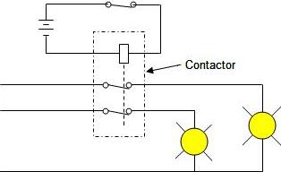
- The second possible application for a contactor is controlling a circuit with one voltage from a circuit with a different voltage, in this example, a battery, as shown in Figure 6.

Figure 6 - Contactor switching 2 separate electrical circuits, powered from an independent circuit
This situation generally arises in a home when low voltage circuits are used to control normal house circuits. In this day and age many items are electronic and powered by low voltage, in many cases batteries.
In a home automation situation there may be an electronic circuit that receives its commands from a wireless control or via computer software. Both of these items use very low voltages to translate push-button or switch actions to having a device switch ON
and OFF
.
The contactor can of course switch more than one circuit and the circuits do not have to be the same voltage. Hence, you could have a situation where by pushing a button on a wireless device you switch a 12VDC circuit on and at the same time switch a 24VAC circuit and a 120VAC circuit ON
.
In summary, an electrical contactor can be an excellent tool to switch multiple circuits from a common source and is probably not utilized as much as it could be in residential applications.
